
Cooling High Heat Flux Devices with Mikros Microchannel Cold Plates
Javier A. Valenzuela, Sc.D.
Thomas J. Jasinski, Ph.D.
Summary
Mikros offers liquid-cooled heat sinks for applications requiring high heat flux cooling and low thermal resistance. Our patented Normal Flow Cold Plate (NCP) can cool devices dissipating as much as 1000 W/cm2 with a thermal resistance per unit area as low as 0.02 °C/(W/cm2). A unique feature of the NCP technology is the ability to eliminate “hot spots” by matching the local thermal resistance of the heat sink to the local heat dissipation of the device being cooled. This capability enables isothermal operation of devices having non-uniform heat dissipation. Demanding applications that would benefit from this cooling technology include: high-end server microprocessors, power electronic components, and high power lasers, to name a few.
Normal Flow Microchannel Cold Plate Performance
Mikros has developed innovative heat sink technology, which retains the high heat flux capability and compact size of traditional microchannel heat sinks, but eliminates their high pressure drop and non-uniform surface temperature.
The principal advantages of the Normal Flow Cold Plate (NCP) technology are:
- Outstanding thermal performance (very low thermal resistance, flow rate, and pressure drop; high thermal effectiveness)
- Unique capability to eliminate “hot spots” by specifying any desired variation of the thermal resistance over the surface of the heat sink
- Compact size

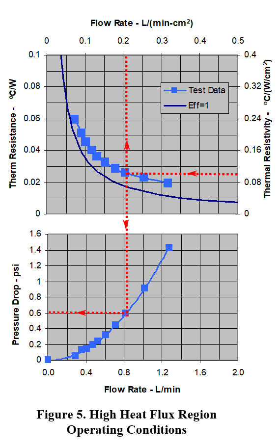
Our first product offering of this technology is a 2 cm x 2 cm NCP suitable for cooling high performance microprocessor chips. The measured performance of this heat sink is shown in Figure 2. The upper half of Figure 2 shows the measured thermal resistance as a function of water flow rate. The scale on the left shows the absolute thermal resistance in °C/W and the scale on the right, the “resistivity” (resistance per unit area) in °C/(W/cm2). The lower half of Figure 2 shows the measured pressure drop as a function of flow rate.
The thermal resistance values possible with the NCP are much lower than can be achieved with other technologies (see Section 3). Low thermal resistance allows high power dissipation at modest temperatures. For example, for a thermal budget of 25 °C this heat sink would have the capacity to cool a 1,200 W load with a flow rate of 1 L/min and a pressure drop of less than 1 psi. These operating conditions correspond to the red dotted lines on Figure 2. The thermal effectiveness at this operating point is 0.6 (yellow dashed line in Figure 2). This means that the temperature rise of the coolant is 60% of the approach temperature difference (25 °C in this case). High thermal effectiveness is important because it results in lower coolant flow rates and lower pressure drops in the rest of the cooling loop. High thermal effectiveness also results in a higher coolant temperature leaving the heat sink, making it easier to cool down the fluid before returning it to the heat sink.
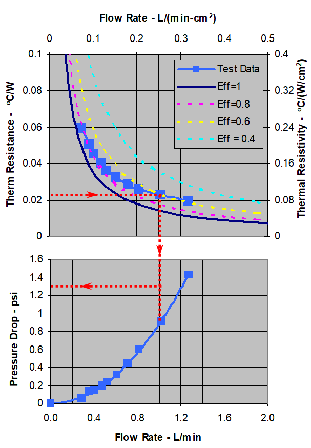
Figure 2. NCP Performance Data
Another advantage of the NCP technology is that its resistivity can be tailored over the surface of the heat sink to eliminate “hot spots.” This ability is an intrinsic characteristic of normal flow heat transfer (see Section 4.) As illustrated in Figure 3, tailoring the thermal resistance to the heat dissipation provides the most effective means of eliminating potential hot spots in applications where the heat generation is highly non-uniform. The thermal resistance of the NCP can be controlled from a low value of about 0.05 °C/(W/cm2) to any higher value with a spatial resolution of about 1 mm.
In addition to its high thermal performance, the NCP is compact and, for most applications, it does not need heat spreaders. The heat transfer matrix is only a few millimeters thick. The size of the flow manifolds depends on the required flow rate, allowable pressure drop, and active area of the heat sink. The heat sink described above has a total thickness of 7.5 mm and a footprint of 23 x 31 mm with, an active area of 20 x 20 mm. As shown in Section 2, this NCP could handle with ease the cooling requirements of present high-end server microprocessors.
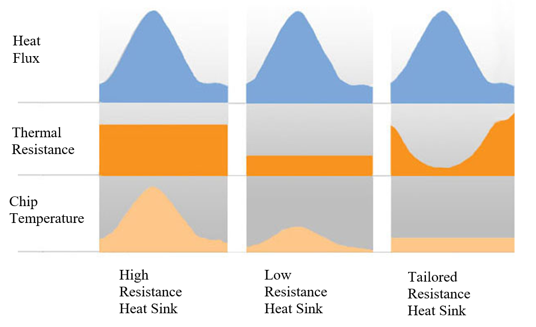
Figure 3. Managing “Hot Spots” With a Tailored Thermal Resistance
Microprocessor Cooling Design Examples
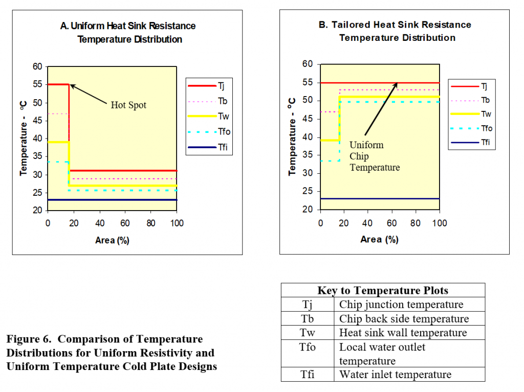
To illustrate the NCP capabilities and to show how this heat sink can be used to manage “hot spots,” we present below two NCP designs for cooling a high performance microprocessor chip. Figure 4 shows the device geometry and the key performance parameters. In this example we have selected the power dissipation of the device to be representative of the anticipated cooling needs of next generation microprocessors. The total power dissipation is 238 W, giving an average heat flux of 59 W/cm2. This microprocessor has an 8×8 mm hot spot at the center of the die dissipating 160 W/cm2, four times the heat flux over the rest of the device. Present air cooled server processors operate at a junction temperatures of about 100 °C [1]. To illustrate the greatly increased cooling capability of a liquid-cooled heat sink, we have reduced the target junction temperature to 55 °C.
We present two designs. The first design employs a heat sink with a uniform thermal resistivity. The value of the thermal resistivity is selected to make the “hot spot” temperature equal to 55 °C. The remainder of the device operates at a substantially lower temperature. The second design employs a heat sink that has the same low thermal resistivity over the “hot spot” area, but a substantially higher resistivity over the rest of the device. The higher resistivity is selected to yield a uniform junction temperature over the entire surface of the chip. To simplify these illustrations, we have neglected the lateral heat spreading resulting from conduction in the silicon chip and in the base of the heat exchanger. This lateral conduction will blend somewhat the transition between the hot spot and the rest of the chip, but the basic results shown below still hold.
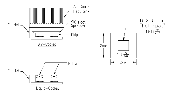
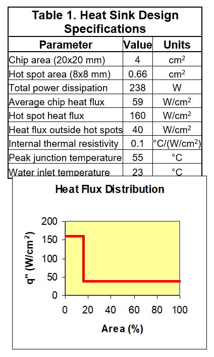
Figure 4. Microprocessor Cooling Requirements
Because of the high performance of the NCP, heat spreading is not required. Hence, both designs assume that the heat sink is embedded in the cover of the Multi-Chip Module. A high conductivity thermal paste (4.5 W/m°C) is used to accommodate slight height variations in the components and to provide a stress-free interface between the heat sink and the chip. A chip thickness of 300 m and an interface thickness of 40 m yields a total internal resistivity of 0.10 °C/(W/cm2).
[1] Schmidt, R. “Changes in Electronic Cooling-Opportunities for Enhanced Thermal Management Techniques”. First International Conference on Microchannels and Minichannels. 2003, Rochester, NY,USAA. Uniform Heat Sink Resistance Design
This heat sink design is driven by the cooling requirements of the “hot spot”. In order to dissipate 160 W/cm2 with a temperature difference of: 55 – 22 = 33 °C, the total resistivity must be less than 0.20 °C/(W/cm2). Since the internal resistivity is 0.10 °C/(W/cm2), the heat sink resistivity must also be no greater than 0.10 °C/(W/cm2). If we were to use the heat sink described in Section 1, we would obtain from Figure 5 a required flow rate of 0.21 L/min-cm2 and a heat sink pressure drop of 0.6 psi. The resulting heat sink performance is summarized in Table 2 and Figure 6.A. This example shows how an “off-the-shelf” NCP can be used to meet the challenging cooling requirements of this application. The resulting package is 1/10th the size of the present air-cooled system and the maximum junction temperature would be 45 °C lower. The coolant flow rate and pressure drop requirements are modest and could easily be met using standard hardware.
B. Uniform Chip Temperature Design
Although the uniform resistivity NCP affords an attractive alternative to air cooling, even further performance improvements can be achieved by customizing the heat sink resistivity to the heat dissipation profile of the chip. In the uniform resistivity design presented above, the chip temperature outside the “hot spot” area is only 31 °C, which is much lower than the allowed 55 °C. As a result, the average temperature rise of the water is only 2.6 °C and the heat sink effectiveness is only 14% – hence the desirability of tailoring the resistivity of the heat sink to match the device cooling requirements. This can be readily accomplished with the NCP because the heat transfer at one location is independent of the heat transfer at any other location, as described in Section 4. Adjusting the local flow per unit area, allows the local heat sink resistivity to be adjusted at will, as shown in Figure 5.
To maintain a constant temperature over the surface of the chip, the total thermal resistivity at any location must be inversely proportional to the local heat flux. Hence, the total resistivity outside the “hot spots” must be Q” = 0.2 * 160 / 40 = 0.8 °C/(W/cm2). Since the internal resistivity is 0.1 °C/(W/cm2), it means that the heat sink resistivity in this region needs to be only 0.7 °C/(W/cm2). This value is outside the range tested, but from Figure 5 one can see that as the resistivity becomes larger than 0.25 °C/(W/cm2), the heat sink effectiveness approaches the theoretical maximum of 1. For the purpose of this example, we assume that the effectiveness has increased to 0.95 at a resistivity of 0.7 °C/(W/cm2).
The resulting heat sink performance is summarized in Table 2 and Figure 6.B. The junction temperature is now constant over the surface of the chip, and the average fluid temperature rise is 15.9 °C.
The substantial benefits of tailoring the heat sink thermal resistivity to match the chip local heat dissipation can be summarized as:
- Factor of 4 decrease in flow (from 0.84 L/min to 0.20 L/min)
- Factor of 1.7 decrease in drop (from 0.6 psi to 0.35 psi)
- Factor of 4 increase in fluid temperature rise (from 3.8 to 15.9 °C)
The reduced flow rate and reduced pressure drop result in a reduction in pumping power by a factor of 7. The reduced flow rate and increased fluid exit temperature greatly facilitate the task of cooling the water down to its inlet temperature for circulation back to the heat sink.
It should be noted that in this example we have not attempted to optimize the heat transfer matrix geometry to meet the requirements of this application. We have simply used the matrix geometry of the present heat sink and tailored the flow manifolds to achieve the desired local resistivity. The resulting heat sink has an overall effectiveness of 57%. As described in Section 3 below, this effectiveness value is quite high when compared to that achieved by other commercially available cold plates. Nevertheless, we believe that customizing the heat transfer matrix for this application would yield perhaps another 10% improvement in effectiveness.
Comparison with other Liquid-Cooled Plates
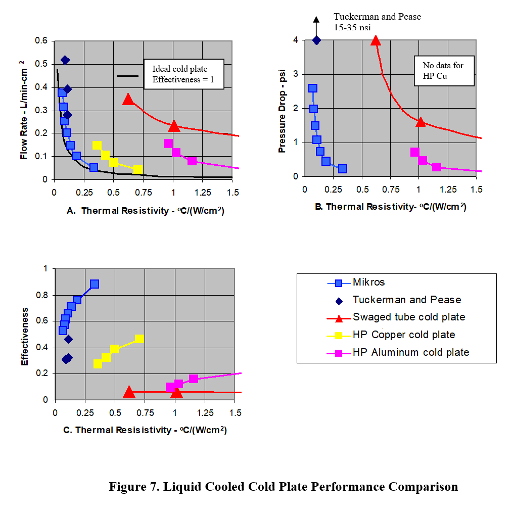
This section presents a comparison of the NCP performance relative to other liquid-cooled cold plates. We include the performance obtained from the vendor literature (water as coolant) for a standard swaged tube aluminum cold plate and two high performance, specialty cold plates:
- Swaged tube cold plate: 2.25”x2.4” aluminum cold plate cooled by a double pass 3/8” diameter copper tube.
- HP aluminum cold plate. Aluminum extrusion with a closely packed array of small diameter openings in a parallel flow arrangement.
- HP copper cold plate. High performance copper cold plate with machined offset fins.
We also include in this comparison the data from the pioneering microchannel heat sink experiments performed by Tuckerman and Peace[1]. That heat sink had 50 m wide, 300 m tall microchannels etched into a silicon wafer with an active cooling area of 1 x 1 cm.
The key performance parameter of a cold plate is its thermal resistivity, defined as the temperature rise of the cold plate heat acquisition surface per unit heat flux absorbed. In this comparison the units of the thermal resistivity are: °C/(W/cm2). The actual thermal resistance in a specific application can be obtained by dividing the resistivity by the cold plate area. That is, if a 2 x 2 cm cold plate has a resistivity of 1 °C/(W/cm2), its thermal resistance would be 0.25 °C/W.
Figure 7.A compares the range of resistivity values that can be achieved with different cold plates. The dashed line on the figure represents the theoretically optimal cold plate performance (lowest resistivity) for a given liquid flow rate. To achieve this performance, the liquid exit temperature would need to be equal to the maximum temperature on the surface of the heat sink. That is, the fluid temperature rise would be equal to the approach temperature difference and the heat sink effectiveness would be equal to 1.
Figure 7.B compares the pressure drop, and Figure 7.C the thermal effectiveness, of the various cold plates as a function of the thermal resistivity.
These results show the remarkable performance of the NCP. Again, the main benefits of the NCP are:
- Very low thermal resistance. Its thermal resistivity is a factor of 2-10 lower than other high performance commercial cold plates and approaches the performance of an ideal cold plate. Its resistivity is even 30% lower than that of microchannels etched on silicon.
- Low pressure drop. The NCP achieves this low resistivity with very low pressure drops, especially when compared to other microchannel cold plates.
- High Effectiveness. The effectiveness of the NCP is several times higher than that of other cold plates. This means that for a given heat load, the flow rates are correspondingly lower and the fluid temperature rise correspondingly higher. The higher fluid temperature rise and lower flow rate greatly simplify the task of dissipating the heat to the atmosphere, the ultimate heat sink for most applications.
Normal Flow Heat Transfer
The outstanding heat transfer performance of the NCP derives from a unique arrangement of the microchannels and internal manifolds that promote normal flow heat transfer. This flow arrangement is part of the patented cold plate technology. This normal flow technology forms the basis of Mikros’ microchannel cold plate technology.
Figure 8 illustrates the difference between a standard microchannel cold plate and a normal flow cold plate. Both cold plates have an array of closely spaced fins that define microchannels. In the standard cold plate, the fluid enters on the left hand side and absorbs heat as it flows between the fins towards the exit manifold placed on the right hand side of the cold plate. The flow direction is parallel to the heat acquisition interface. The corresponding temperature distributions on the fluid and the fins are shown on the left hand side of Figure 8. It is assumed in this example that the heat flux is uniform over the surface of the cold plate, as indicated by the uniform temperature drop across the base of the cold plate. The temperature at the base of the cold plate, however, is not uniform because the fluid is heating up as it moves along the passages. The temperature of the fluid leaving the microchannels is also not uniform since the fin temperature will be cooler further away from the base of the cold plate.
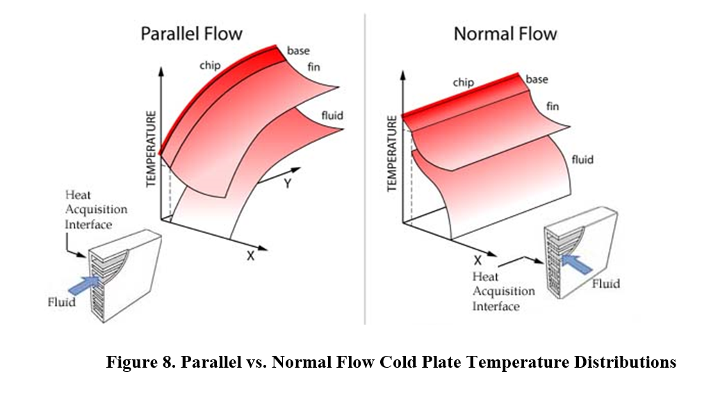
The normal flow arrangement is illustrated on the right hand side of Figure 8. In this configuration, the fluid enters on the top of the fins and flows between the fins towards the heat acquisition interface, where it is collected in distributed manifolds (not shown in the Figure). The flow direction is normal to the heat acquisition interface. The resulting fluid and fin temperature distributions are shown on the right hand side of Figure 8. In the normal flow arrangement both the temperature at the base of the cold plate and the exit fluid temperatures are uniform over the surface of the cold plate, in contrast to the variable temperatures in the parallel flow arrangement.

The principal characteristics of the normal flow arrangement are:
- Local heat transfer is independent of heat transfer in other regions of the cold plate. In the parallel flow arrangement the cooling ability of the flow is continually decreasing along the length of the channel. Hence, the wall temperature near the exit side is higher than near the entrance side. In the normal flow arrangement, each region of the cold plate receives fluid at the same temperature. This means that the cooling potential is the same throughout the surface of the cold plate. It also means that one can change the local resistivity in one region by varying the local flow rate, without affecting other regions of the cold plate.
- Low fluid velocities. In the parallel flow arrangement, all the flow must travel through the thin microchannel layer adjacent to the heat transfer interface. This layer must remain thin because the temperature gradient on the fins reduces the cooling ability of the fluid flowing furthest from the heat acquisition interface. In contrast, in the normal flow arrangement, the flow can occupy the entire area of the cold plate. Flow velocities are an order of magnitude lower in the normal flow configuration than in the parallel flow configuration.
- Short flow passages. In the parallel flow arrangement, the flow passage length is determined by the size of the device being cooled. This length can be as much as 2 cm in high performance processors and even larger in high capacity IGBTs. In contrast, in the normal flow arrangement, the flow passage length is independent of the size of the device being cooled and can be chosen to optimize the performance of the cold plate. Since most of the heat transfer takes place in a thin layer close to the heat acquisition interface, the flow passages in the normal flow arrangement are typically an order of magnitude shorter than in the parallel flow arrangement.
These characteristics of the normal flow arrangement endow the NCP with the advantages highlighted in Sections 2 and 3, namely:
- Excellent thermal performance. Low fluid velocities combined with short flow passages allow the use of very narrow passages without incurring excessive pressure drop. Narrow passages, in turn, increase the surface area per unit volume and the fluid heat transfer coefficient. As was shown in Section 3, the net result is that a Normal Flow Cold Plate excels in all three key performance paramenters: the NCP can simultaneously achieve very low resistivity, low pressure drop, and high thermal effectiveness. The high thermal effectiveness results in low flows. Low flow rates and high fluid exit temperatures greatly simplify the design of the remainder of the thermal management system.
- Ability to eliminate “hot spots”. The independence of the local heat transfer from the heat transfer in other regions of the cold plate makes it possible to optimize the performance of the cold plate by tailoring the local resistivity to the heat dissipation profile of the device being cooled. As shown in the design example in Section 2, tailoring the cold plate resistivity is a very effective means for eliminating “hot spots” and, in addition, it can result in a several-fold increase in cold plate effectiveness, and reduction in flow rate and pressure drop.
- Compact size and low cost. The very low resistivity possible with the NCP, coupled with the ability to tailor the local resistivity, eliminate the need to use heat spreaders. The footprint of the NCP need not be any larger than that of the device being cooled. The small size of the NCP cold plate will enable the designer to increase the packing density of the electronic components and will also reduce the cost of the cold plate. In fact, in devices having a hot spot surrounded by lower heat dissipation areas, it may be advantageous to use a heat concentrator to further reduce the size and cost of the cold plate.
- Performance independent of size and geometry. Since the length of the flow passages and the local fluid temperatures are independent of the size of the device, the NCP can be used to cool devices of arbitrary size and geometry.
About Mikros and Mikros Thermal Systems
Mikros Technologies was founded by Dr. Javier Valenzuela in 1991 to commercialize micro-EDM technology developed under an SBIR project for NASA Johnson Space Center. That project involved the development of a droplet-impingement evaporator and single-phase microchannel matrices for thermal management on board the Space Station.
Today, Mikros designs, tests and manufactures optimized miconozzles and thermal management solutions for a wide range high heat flux applications including high performance computing, power electronics, LEDs, lasers, and more. Our patented Normal Flow microchannel and mini-channel liquid cold plates provide industry-leading low thermal resistance and pressure drop, giving designers greater thermal budgets to improve the performance, packaging, and reliability of their systems.
The Mikros Team prides itself on being a strong development partner, designing solutions from first principles of fluid mechanics and thermodynamics to client priorities, helping engineers get the most from their high power systems where theraml demands are a critical system limitation.
For further information regarding Mikros liquid cooled NCP heat sinks please contact us at 603-690-2020 or info@mikros.net
More Power To You.